
• In pure water systems, electrolytic conductivity or resistivity measurement is the most common indicator of ionic contamination. The same basic measurement is read out in either conductivity units of micro siemens per centimeter (μS/cm), typical of the pharmaceutical and power industries or in resistivity units of megohm-centimeters (Mohm•cm) used in the microelectronics industries. These units are reciprocals of each other. Absolutely pure water has a conductivity of 0.05501 μS/cm and a resistivity of 18.18 Mohm•cm at 25 °C, the most common reference temperature to which these measurements are compensated. An example of the sensitivity to contamination of these measurements is that 0.1 ppb of sodium chloride raises the conductivity of pure water to 0.05523 μS/cm and lowers the resistivity to 18.11 Mohm•cm
• Ultrapure water is easily contaminated by traces of carbon dioxide from the atmosphere passing through tiny leaks or diffusing through thin wall polymer tubing when sample lines are used for measurement. Carbon dioxide forms conductive carbonic acid in water. For this reason, conductivity probes are most often permanently inserted directly into the main ultrapure water system piping to provide real-time continuous monitoring of contamination. These probes contain both conductivity and temperature sensors to enable accurate compensation for the very large temperature influence on the conductivity of pure waters. Conductivity probes have an operating life of many years in pure water systems. They require no maintenance except for periodic verification of measurement accuracy, typically annually.
1) Ion Exchange Process
Process utilizing special-manufactured ion exchange resins which remove ionised salts from water. Can theoretically remove 100 % of salts. Deionization typically does not remove organics, virus or bacteria except through “accidental” trapping in the resin and specially made strong base anion resins which will remove gram-negative bacteria. Another possible process to create deionized water is electrode ionization.
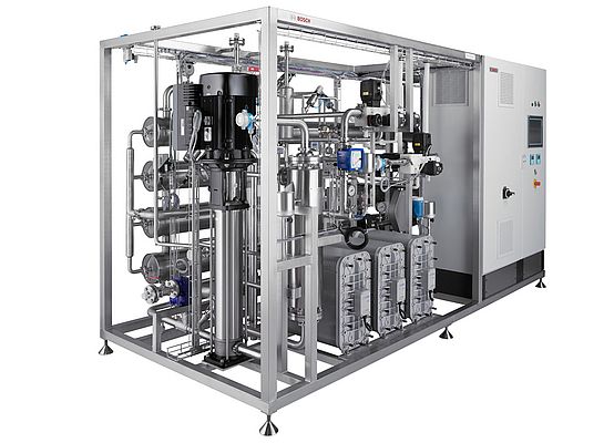
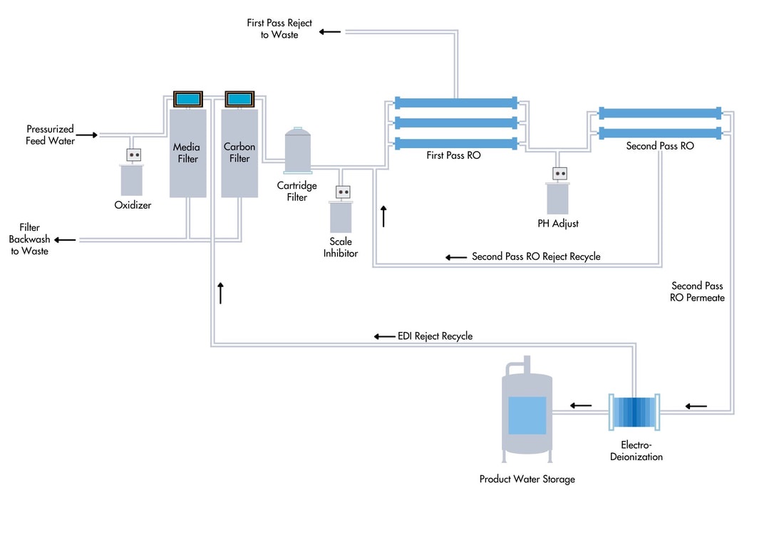
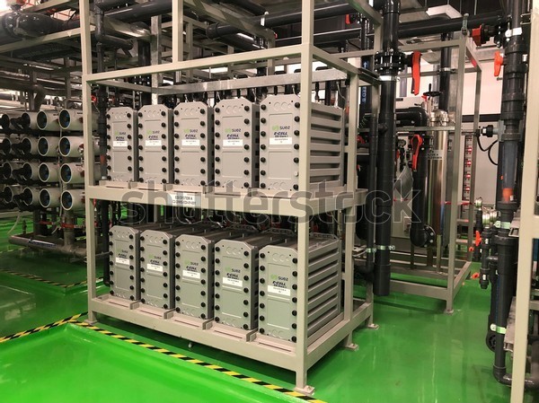
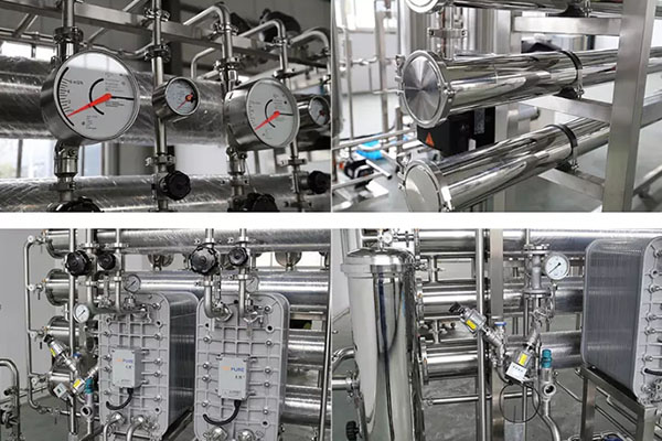
2) RO+EDI Water Treatment Systems
Simplify operations with high purity results by combining RO with EDI
Other applications include use with boiler feed water and for the replacement of aging ion exchange systems.
Combining a reverse osmosis (RO) system and an E-Cell electrode ionization (EDI) system. This design offers customers installation simplicity, ease of operation, and smaller footprint,
Alleviates bulk acid and caustic environment, health & safety concerns regarding when replacing an aging ion exchange system.
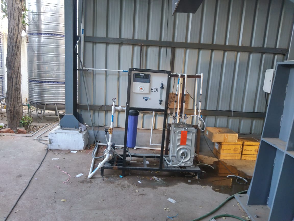
Working Principle of EDI
In electrodialysis, electrical current drives ions across a semipermeable membrane. In an EDI system, a membrane that allows for the passage of cations (OH- ions) only is positioned next to the cathode, and a membrane permeate to anions (H+ ions) only is positioned next to the anode.

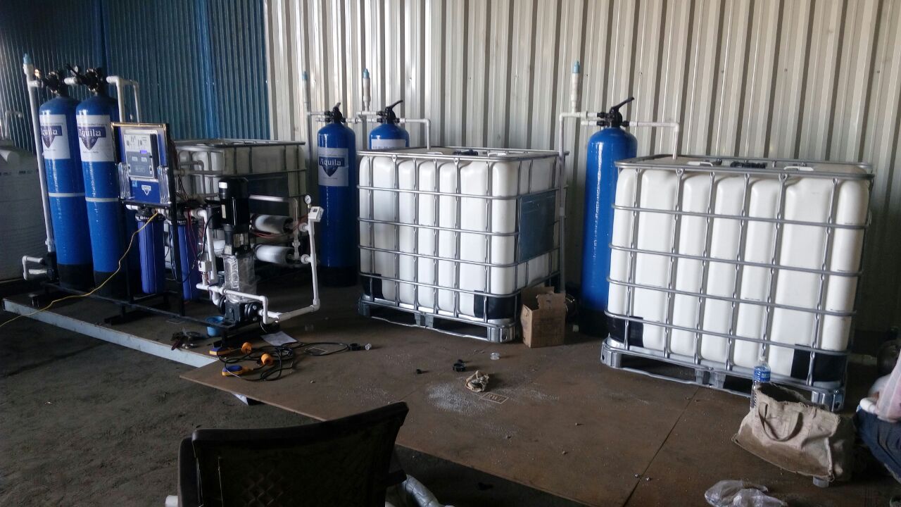
| D.M Plant + Mixed Bed Plant | LINK |
| Reverse Osmosis Plant + D.M Plant + Mixed Bed Plant | LINK |
| 2 Pass RO Plant + Electro Deionization Plant. (EDI | LINK |
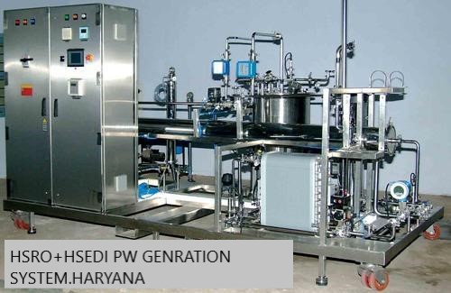
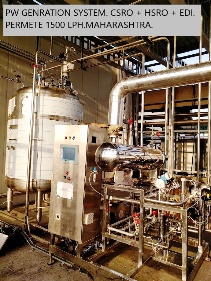
| CSRO+HSRO + HSEDI (H.S = Hot Water Sanitizable) | LINK |
| We Offer Customized Treatment Scheme Based on Inlet Water Characteristics And Permeate Water Requirement. | LINK |
Sodium is usually the first ion to break through a depleted cation exchanger. Sodium measurement can quickly detect this condition and is widely used as the indicator for cation exchange regeneration. The conductivity of cation exchange effluent is always quite high due to the presence of anions and hydrogen ion and therefore conductivity measurement is not useful for this purpose. Sodium is also measured in power plant water and steam samples because it is a common corrosive contaminant and can be detected at very low concentrations in the presence of higher amounts of ammonia and/or amine treatment which have a relatively high background conductivity.
On-line sodium measurement in ultrapure water most commonly uses a glass membrane sodium ion-selective electrode and a reference electrode in an analyzer measuring a small continuously flowing side-stream sample. The voltage measured between the electrodes is proportional to the logarithm of the sodium ion activity or concentration, according to the Nernst equation. Because of the logarithmic response, low concentrations in sub-parts per billion ranges can be measured routinely. To prevent interference from hydrogen ion, the sample pH is raised by the continuous addition of a pure amine before measurement. Calibration at low concentrations is often done with automated analyzers to save time and to eliminate variables of manual calibration.
Advanced microelectronics manufacturing processes require low single digit to 10 ppb dissolved oxygen (DO) concentrations in the ultrapure rinse water to prevent oxidation of wafer films and layers. DO in power plant water and steam must be controlled to ppb levels to minimize corrosion. Copper alloy components in power plants require single digit ppb DO concentrations whereas iron alloys can benefit from the passivation effects of higher concentrations in the 30 to 150 ppb range.
Dissolved oxygen is measured by two basic technologies: electrochemical cell or optical fluorescence. Traditional electrochemical measurement uses a sensor with a gas-permeable membrane. Behind the membrane, electrodes immersed in an electrolyte develop an electric current directly proportional to the oxygen partial pressure of the sample. The signal is temperature compensated for the oxygen solubility in water, the electrochemical cell output and the diffusion rate of oxygen through the membrane.
Optical fluorescent DO sensors use a light source, a fluorophore and an optical detector. The fluorophore is immersed in the sample. Light is directed at the fluorophore which absorbs energy and then re-emits light at a longer wavelength. The duration and intensity of the re-emitted light is related to the dissolved oxygen partial pressure by the Stern–Volmer relationship. The signal is temperature compensated for the solubility of oxygen in water and the fluorophore characteristics to obtain the DO concentration value.
Silica is a contaminant that is detrimental to microelectronics processing and must be maintained at sub-ppb levels. In steam power generation silica can form deposits on heat-exchange surfaces where it reduces thermal efficiency. In high temperature boilers, silica will volatilize and carry over with steam where it can form deposits on turbine blades which lower aerodynamic efficiency. Silica deposits are very difficult to remove. Silica is the first readily measurable species to be released by a spent anion exchange resin and is therefore used as the trigger for anion resin regeneration. Silica is non-conductive and therefore not detectable by conductivity.
Silica is measured on side stream samples with colorimetric analyzers. The measurement adds reagents including a molybdate compound and a reducing agent to produce a blue silico-molybdate complex color which is detected optically and is related to concentration according to the Beer–Lambert law. Most silica analyzers operate on an automated semi-continuous basis, isolating a small volume of sample, adding reagents sequentially and allowing enough time for reactions to occur while minimizing consumption of reagents. The display and output signals are updated with each batch measurement result, typically at 10 to 20-minute intervals.
Particles in UPW have always presented a major problem for semiconductor manufacture, as any particle landing on a silicon wafer can bridge the gap between the electrical pathways in the semiconductor circuitry. When a pathway is short-circuited the semiconductor device will not work properly; such a failure is called a yield loss, one of the most closely watched parameters in the semiconductor industry. The technique of choice to detect these single particles has been to shine a light beam (a laser) through a small volume of UPW and detect the light scattered by any particles (instruments based on this technique are called laser particle counters or LPCs). As semiconductor manufacturers pack more and more transistors into the same physical space, the circuitry line-width has become narrow and narrower. As a result, LPC manufacturers have had to use more and more powerful lasers and very sophisticated scattered light detectors to keep pace. As line-width approaches 10 nm (a human hair is approximately 100,000 nm in diameter) LPC technology is becoming limited by secondary optical effects, and new particle measurement techniques will be required. Recently, one such novel analysis method named NDLS has successfully been brought into use at Electrum Laboratory (Royal Institute of Technology) in Stockholm, Sweden. NDLS is based on Dynamic Light Scattering (DLS) instrumentation.
Another type of contamination in UPW is dissolved inorganic material, primarily silica. Silica is one of the most abundant mineral on the planet and is found in all water supplies. Any dissolved inorganic material has the potential to remain on the wafer as the UPW dries. Once again this can lead to a significant loss in yield. To detect trace amounts of dissolved inorganic material a measurement of non-volatile residue is commonly used. This technique involves using a nebulizer to create droplets of UPW suspended in a stream of air. These droplets are dried at a high temperature to produce an aerosol of non-volatile residue particles. A measurement device called a condensation particle counter then counts the residue particles to give a reading in parts per trillion (ppt) by weight.[28]
Total organic carbon is most commonly measured by oxidizing the organics in the water to CO2, measuring the increase in the CO2 concentration after the oxidation or delta CO2, and converting the measured delta CO2 amount into "mass of carbon" per volume concentration units. The initial CO2 in the water sample is defined as Inorganic Carbon or IC. The CO2 produced from the oxidized organics and any initial CO2 (IC) both together are defined as Total Carbon or TC. The TOC value is then equal to the difference between TC and IC.